INTRODUCTION
The Composite Step Signal comprises of predefined test signal components which are fused together to generate a desired test pattern (van Roermund and Snijder, 1989). The Composite Signal may have wide range of results ranging from a video picture of a distant data to the digital information, corresponding to the outcome of a complex measurement system. The signal or data transmitted by the Composite Signal becomes the input signal for various data processing or data acquisition systems. The interpretation of data depends upon the purity of the data/signal transmitted. The transmission of the Composite Signals is carried out by utilizing various transmission channels and mediums. The selection of transmission channel depends on the type of information being transmitted through the Composite Signal. During the propagation of the signal, noise gets introduced in the Test Signal (Saupe and Xiong, 2004). This noise signal mixes with the core signal and becomes a part of the transmitted Composite Signal. The noise affects various signal components of the Composite Signal and becomes an integral part of the signal itself. As a result the overall attributes of the test signal system gets corrupted (Chen et al., 2009). The noise detection techniques have to be applied to detect the type and presence of noise. The selection of noise detection techniques becomes very crucial as selection of noise reduction methods depends on it. The noise detection techniques have direct impact on the noise reduction algorithm. The main obstacle in the field of noise detection is to effectively differentiate the noise signal patterns from the Test Signal patterns/ waveforms. The noise patterns introduced in the Composite Signal are very similar to the true signal patterns. Careful investigation is needed to differentiate noise patterns in the signal. To analyze the noise patterns in Step Composite Signal, oscilloscope with wide band width is utilized. An oscilloscope with band width of 200 MHz is most suitable for the purpose of analysis (Punchihewa et al., 2004). The oscilloscope provides the information of the Composite Signal waveforms and its analysis reveals the noise affected signal components.
COMPONENTS OF COMPOSITE STEP SIGNAL
Composite Signals contains information of test sequences, required to adjust and evaluate a display screen. It contains vital and important signal components. Each component has a specific role and it contains information of a test sequence. The components of the signal possess unique attributes in terms of amplitude and frequency. Each portion of the Composite Step Signal can be accessed and modified as per the requirement of the test sequence. The modification of the components of the signal is performed by altering core signal generation program with the help general purpose interface bus communication mode. Figure 1 represents the waveforms of Composite Step Signal.
Above Figure 1 illustrates the Composite Step Signal which comprises of luminance signal, chrominance signal and synchronization pulses. The peak to peak amplitude of the signal is expressed in the form of volts per division of the Oscilloscope. The variation in the amplitude of the signal component alters the overall performance of the test signal.
NOISE DETECTION IN COMPOSITE STEP SIGNAL
The procedure of noise recognition in Composite Step Signals is complex as the noise is embedded with in the signal and its components. The noise may or may not alter the overall amplitude and pulse width of the signal wave form. The changes in the overall peak to peal signal amplitude may be very small but the change in the values of the individual signal constituents may be of major concern. The changes in the properties of the Composite Signal constituents change the final test image/signal (Poynton, 2012).
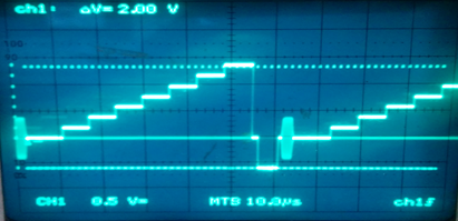
The waveform of the Composite Step Signals is analyzed with the help of an oscilloscope. The oscilloscope having a band width of 200 MHz is preferred as it is allows to capture and analyze the small details of the Composite Signal constituents. The signal generator which produces Composite Step Signal is connected to the input of the oscilloscope to observe the waveform of the signal. Figure 2 represents the captured image on the oscilloscope of the Composite Step Signal, generated by a Complex signal generator (Ryoichi, 2004; Shahid et al., 2014).
In Figure 2, the waveform of Composite Step Signal indicates the signal constituents such as:
Luminance Signal
Synchronization Pulses
Chrominance Signal
The waveform observed on oscilloscope is free from any type of noise. All the signal constituents of the waveforms are clearly visible on an oscilloscope.
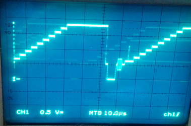
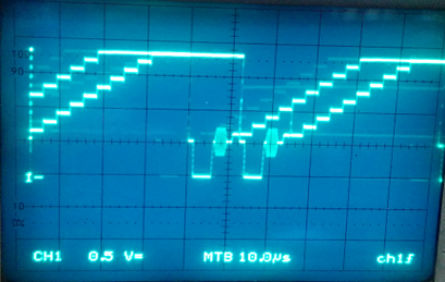
The oscilloscope is connected at the final out put stage, known a receiver end to analyze the transmitted waveform. It is observed that Composite Step Signal is affected with noise which appears as a "Ghost image" of the Step Signal. The noise may be introduced to the signal at the time of transmission or due to the limitations of the devices being used for signal processing (Lee et al., 2007).
Figure 3 represents waveforms of the distorted Composite Step Signal (Lee et al., 2008). The waveform at the final stage is compared with the waveforms of Composite Step Signal Generator at the point of transmission (Tanaka, 2006). The comparative analyses shows that the signal constituents at the final stage is affected by the ghost image of Composite Step Signal. The presence of ghost signal alters the standard signal components from its actual values to a new distorted values (Peiravi and Toosizadeh, 2009). These new values acquired by the Step Composite Signal corrupts the actual signal/information transmitted (Harada and Oritake, 1982). The noise in the signal produces undesirable effects on the final results of the signal. Thus the motive to transmit the information is lost (Hooper and Sunnyvale, 1986). The analyses of waveforms on an oscilloscope reveals the type and characteristics of noise (Punchihewa, 2003). The analysis of Step waveforms indicates that peak to peak amplitude of the Composite Step Signal has not changed. It is also being noticed that the pulse width of the signal also remains unchanged. The observations help to select the effective method for noise reduction.
CONCLUSION
The characteristics and attributes of the noise in Step Composite Signal waveforms are analyzed and detected by observing the waveforms on an oscilloscope. The type of noise and its impact on the Step Composite Signal can be estimated well by signal waveform analysis. The reduction of noise is targeted to the noise affected portions of the Composite Step Signal. Thus it is not required to process the entire signal for the reduction of noise. The estimation of noise by this method helps to suggest and evaluate remedial noise reduction steps which introduces minimum artefacts and maintains good signal quality and preserve its original characteristics. The original characteristic of the signal ranges from a remote sensing data to images transmitted by a satellite. The noise reduction helps to restore the original transmitted data for the signal processing in order to obtain correct information transmitted from the source.

 Full Text (PDF)